| Version 3 (modified by , 11 years ago) ( diff ) |
|---|
HTC Evo 4G (model: PC36100)
Chassis Manager (CM) Connector
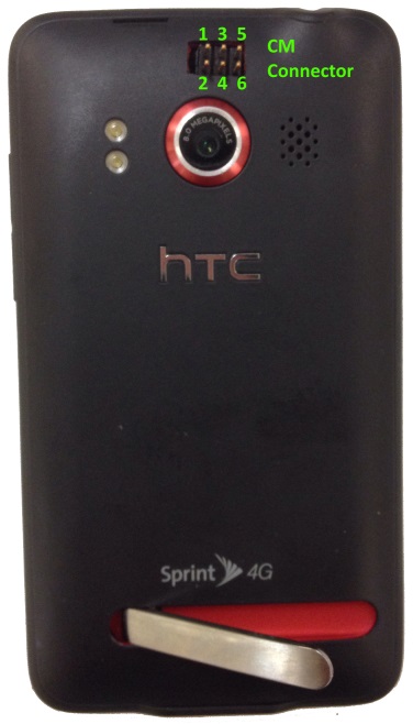
The CM connector is a standard 3x2 0.100" header. It is located on the back of the phone above the rear camera lens. Pin 1 is in the upper left corner. Refer to Table 1 for connector pinout.
| Pin | Function |
| 1 | Power - ground |
| 2 | Power - signal |
| 3 | Volume Up - signal |
| 4 | Volume Up - signal |
| 5 | Volume Down - ground |
| 6 | Volume Down - signal |
Table 1: CM Connector Pinout
Chassis Manager (CM) Compatibility Modification
NOTE: All steps assume a device orientation where the "top" is the edge of the phone with the headphone jack, and the "bottom" is the edge with the USB and HDMI ports.
Phone Disassembly:
- Pry off back cover starting at the top.
- Remove battery.
- Unlock and remove SD Card.
- Remove 6x T-5 Torx screws.
- Separate the front and back of the phone by prying them apart along the edge (the black border around the red is part of the back half).
Adding CM Connector:
- Remove 1x Phillips screw in the top left of the PCB (by headphone jack).
- Gently lift the PCB from the right side using the cables on the left as a "hinge" until the PCB is at 90 degrees to the screen.
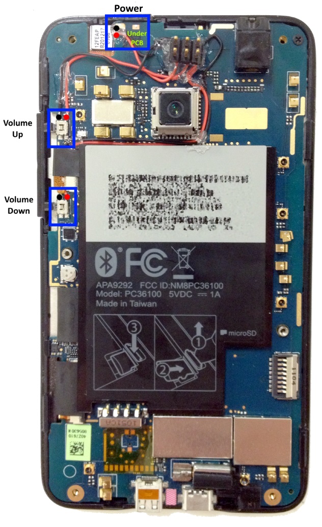
- Locate the power button on the under side of the PCB. It is at the top nearest the notch in the PCB (see Figure 2).
- Solder 2 wires to the power button pads nearest the notch in the PCB. Looking at the power button, the top-right pad is ground, the bottom-right pad is the signal.
- Place the PCB back down against the screen and reattach the screw removed in step 1.
- Locate the Volume Up button on the right edge of the PCB (see Figure 2). It is just above the orange ribbon cable.
- Solder 2 wires to the top 2 pads. The top-left pad is ground, the top-right pad is the signal.
- Locate the Volume Down button on the right edge of the PCB (see Figure 2). It is just below the orange ribbon cable.
- Solder 2 wires to the top 2 pads. The top-left pad is ground, the top-right pad is the signal.
- Route all wires to the area just above the rear camera (use hot glue or tape as needed).
- Solder the wires to a 3x2 0.100" header as described in the Table 1 CM Connector Pinout.
- Hot glue the CM Connector to the PCB.
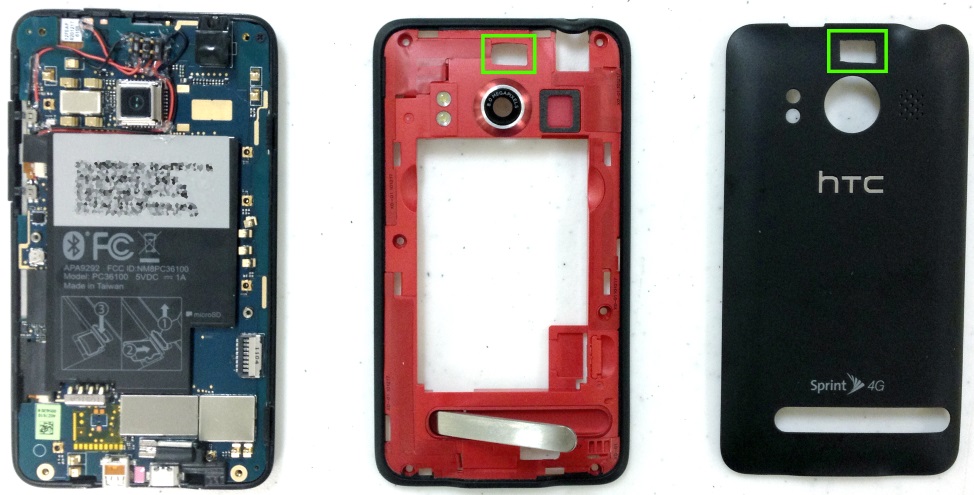
- Cut/drill a hole in the red half of the phone as in Figure 3.
- Looking at the underside of the read half:
- Discard the black rubber gasket around the speaker on the red half of the phone (see Figure 4).
- Cut off the 0.5cm tab at the bottom of the top-right screw hole.
- Cut/drill a hole in the black back cover of the phone as in Figure 3.
- Reassemble the phone by following the reverse of the disassembly steps above.
 |  | |
| Figure 2 | Figure 3 | Figure 4 |
Testing CM Connector:
- Short pins 1-2 momentarily, the phone should start booting up.
- Once the phone boots up, unlock it to the home screen.
- Short ping 3-4 momentarily, the screen should indicate volume being increased.
- Short pins 5-6 momentarily, the screen should indicate volume being decreased.
- As a final step, test the power and volume up/down buttons themselves.
Attachments (4)
- phone - all parts diagram.jpg (146.4 KB ) - added by 11 years ago.
- phone - gasket.JPG (12.3 KB ) - added by 11 years ago.
- phone - complete diagram.jpg (53.8 KB ) - added by 11 years ago.
- phone - pcb diagram.jpg (233.5 KB ) - added by 11 years ago.
Download all attachments as: .zip
Note:
See TracWiki
for help on using the wiki.

