| Version 5 (modified by , 9 years ago) ( diff ) |
|---|
FCI Antenna
Most of the info on this page is proprietary and confidential to the manufacturer. Do not distribute!!!
Hardware
IO Port
| Pin | Name | Direction | Description |
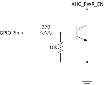
| 2 | AHC_PWR_EN | IN | Connect to DGND to turn off the antenna head, leave floating (or pull to 12V) to turn on antenna head |
| 3 | PAT_CLK_232 | OUT | RS232 Levels, Antenna pattern change indicator |
| 5 | DGND | ||
| 9 | EXT_TX_232 | IN | RS232 Levels, Switch antenna between TX and RX, also requires commands via the CMD interface |
To turn the antenna on/off using a Raspberry Pi or other microcontroller, the AHC_PWR_EN pin must be connected to ground through an NPN transistor as follows:

|
In addition, the "array enable" command must be sent after power on otherwise no further communication can take place. Note that after power on, the serial buffer may contain garbage bytes which may prefix the response of the "array enable" command.
NOTE: When controlling the antenna directly from a USRP X310, the serial port state machine of the USRP may fail when the antenna is power cycled (rarely) or during certain other scenarios. Noise on the RS485 connection may falsely be interpreted as data causing the state machine to lockup. Current solution is to reflash the UHD image.
Software API
Serial port config: 115200bps baudrate, 8 bit data, no parity, 1 stop bit, no flow control
The commands work the same way over either the RS232 or the RS485 (originally via a USB adapter board) connections.
Commands
| Name | Format | Response |
| Configure Power Amp | <addr>x<padrive>:<txgain> | drive: … |
Attachments (1)
- ahc_pwr_en.png (3.7 KB ) - added by 9 years ago.
Download all attachments as: .zip
