| Version 10 (modified by , 6 years ago) ( diff ) |
|---|
LTE Traffic Trace Collection
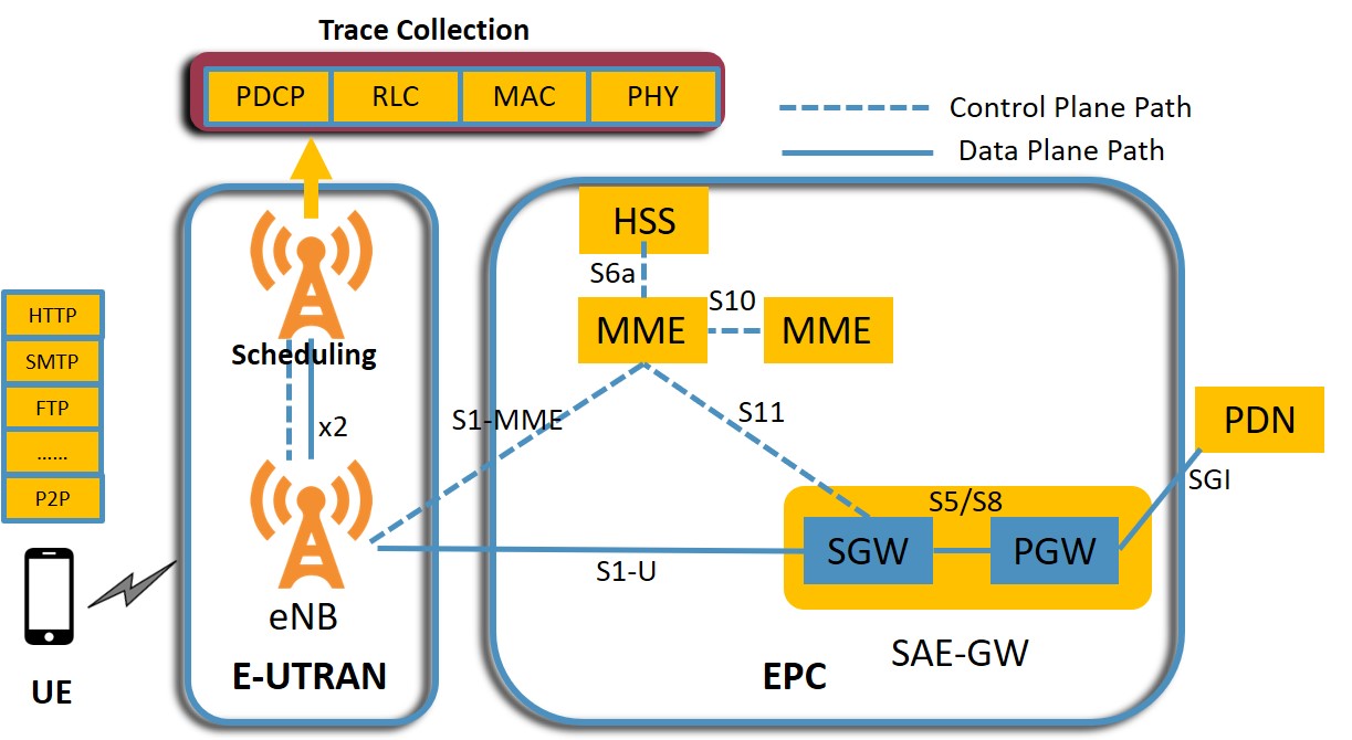
This wiki page contains the tutorial to collect traffic traces for realtime application such as video, web, mail services etc. at RLC, MAC and PDCP layer of LTE protocol stack in ORBIT testbed using OpenAirInterface (OAI) emulation platform. Users were connected over the air using b210 USRP and data/logs recorded at eNodeB (eNB) were extraced using standard linux tools. A high level system diagram is given below.
| Figure 1: System Diagram - Trace Collection |
Description
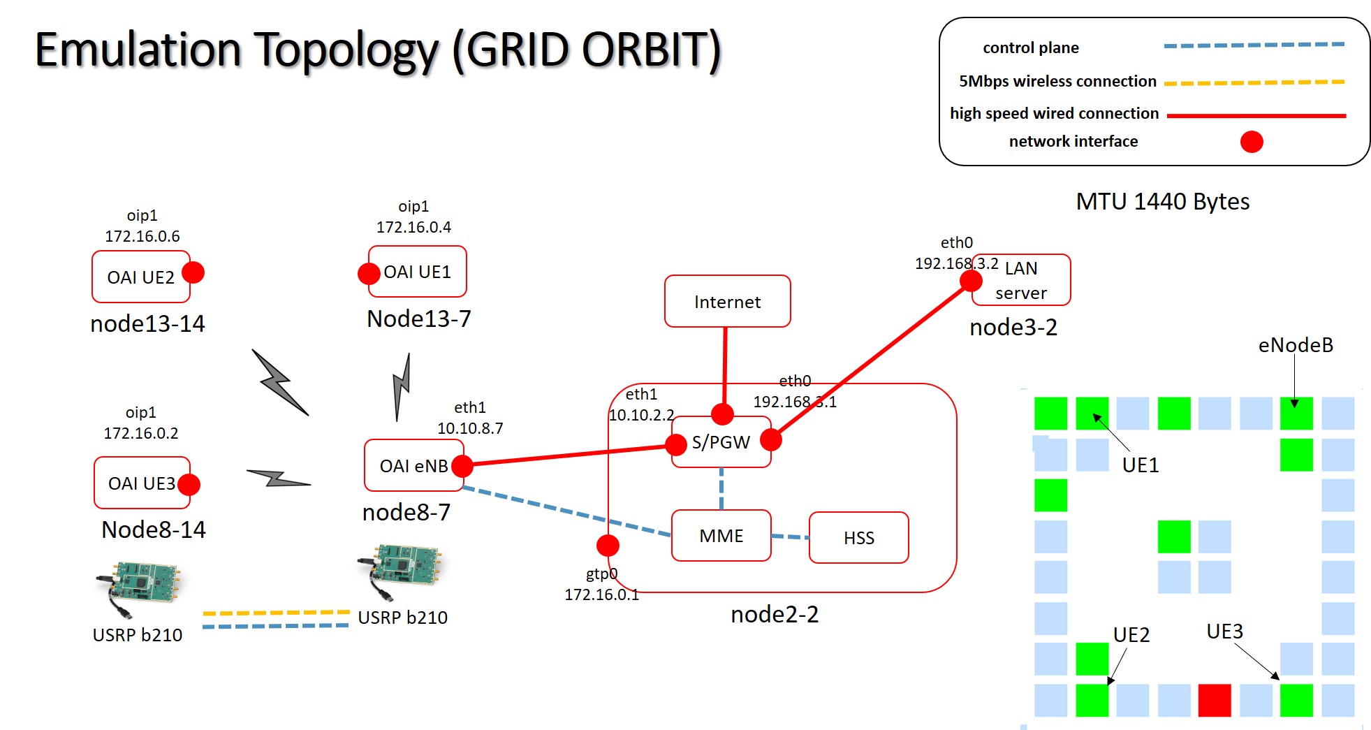
For this experiments we need UEs (User Equipment), eNB having b210 USRP, two other nodes for EPC (Evolved Packet Core) and a server to test connectivity and bandwidth. We have used grid sandbox with node8-7 as eNB; node13-7, node13-14 and node8-14 as UEs; node2-2 as EPC; node3-2 as server. More users can be added but we have tested with just 3 users in this experiment. A detailed system diagram with list of all the attached interfaces is given below. This tutorial will cover following sections:
- Setup OAI emulation framework
- Connecting UE to LTE network
- Connecting Multiple UEs
- Running OAI logging Module
- Application Design
- Trace collection and Evaluation
- OAI run using scripts (github link)
| Figure 2: GRID OAI System Design Implementation for 3 users - Trace Collection |
Setup OAI emulation framework
1) Loading an image into ORBIT node
- Loading UE image:
UE1:omf load -i ue1.ndz -t node13-14
UE2:omf load -i ue2.ndz -t node13-7
UE3:omf load -i ue3.ndz -t node8-14
- Loading eNB image:
eNB:omf load -i enb.ndz -t node8-7
- Loading EPC image:
EPC:omf load -i epc.ndz -t node2-2
- Loading Server image:
Server:omf load -i baseline.ndz -t node3-2
After loading the image turn on the nodes using command: omf tell -a on -t node13-14,node13-7,node8-14,node8-7,node3-2,node2-2
2) Starting EPC :
Run the following commands to enable eth0 interface and to start EPC components - HSS, MME and SPGW:
ssh root@node2-2
cd /root/openair-cn/SCRIPTS
ifconfig eth0 192.168.3.1/24 up
./run_hss
./run_mme
./run_spgw
3) Configuring Server
ssh root@node3-2
ifconfig eth0 192.168.3.2/24 up
ip route add 172.16.0.2 via 192.168.3.1
4) Starting eNB:
ssh root@node8-7
ifconfig eth1 mtu 1440
cd /root/openairinterface5g/cmake_targets/lte_build_oai/build
sudo -E ./lte-softmodem -P /tmp/oai_enb.pcap -O /root/openairinterface5g/targets/PROJECTS/GENERIC-LTE-EPC/CONF/enb.band7.tm1.25PRB.usrpb210.conf --T_nowait
Connecting UE to LTE network
Considering UE1
ssh root@node13-14
cd /root/openairinterface5g/cmake_targets/tools/
source ./init_nas_s1 UE
cd /root/openairinterface5g/targets/bin
sudo -E ./lte-softmodem.Rel14 -U -C2685000000 -r25 --ue-scan-carrier --ue-txgain 70 --ue-rxgain 80 -W
In a separate terminal
ssh root@node13-14
sudo ifconfig oip1 up
ifconfig oip1 mtu 1440
route add default gw 172.16.0.2
The Tx and Rx gain has to adjusted based on physical distance between UE and eNB. Same procedure is repeated if you want to add UE2 and UE3 but the IP address will be different. IP address assignment by MME depends on when the UE is attached to network. If UE1, UE2 and UE3 are attached sequentially then their IP address will be 172.16.0.2, 172.16.0.4 and 172.16.0.6 respectively. This IP assignment can be easily checked using ifconfig
Connecting Multiple UEs
More users can also be connected for a realistic LTE scenario. Apart from the nodes used above node18-2, node18-19 and node3-19 have USRPb210 and can be used to emulate UE. The same UE image can be used but we have to change IMSI and MSISDN for newly added UEs. The following procedure has to be followed to add multiple UE :
- Remove any existing UE with same IMSI from HSS database (remember IMSI).
- IMEI should be different for different users. Take the same IMEI from HSS database, add it to config of UE but while adding in database (DB) again, make it null (IMP).
- Add in database using the command below with IMSI, MSISDN
ssh root@node2-2 (EPC) mysql -u root -p linux INSERT INTO users (`imsi`, `msisdn`, `imei`, `imei_sv`, `ms_ps_status`, `rau_tau_timer`, `ue_ambr_ul`, `ue_ambr_dl`, `access_restriction`, `mme_cap`, `mmeidentity_idmmeidentity`, `key`, `RFSP-Index`, `urrp_mme`, `sqn`, `rand`, `OPc`) VALUES ('To be changed', 'To be changed', NULL, NULL, 'NOT_PURGED', '120', '50000000', '100000000', '47', '0000000000', '7', 0x8BAF473F2F8FD09487CCCBD7097C6862, '1', '0', '', 0x00000000000000000000000000000000, ''); - At UE change and build the config file as below:
./conf2uedata -c ~/openairinterface5g/openair3/NAS/TOOLS/ue_eurecom_test_sfr.conf -o ~/openairinterface5g/targets/bin
- Build the UE again using:
source ./init_nas_s1 UE
Enabling OAI logging Module
To collect the trace we need to enable T tracer present in OAI before starting the application and eNB. The following command is used to obtain the trace at eNB:
cd /root/openairinterface5g/common/utils/T/tracer;./textlog -d ../T_messages.txt -ip 0.0.0.0 -on MAC -on RLC -on PDCP -on RRC -no-gui > /var/log/enbtracer.log 2> /var/log/enbtracer.log &
With the above command, traces will be collected at MAC, RLC , PDCP and RRC layer which will be dumped in enbtracer.log file present at /var/log directory.
Application Design
1) Test Application
- Ping and Perf: These standard linux utility tools were used in our experiment of trace extraction. Ping is a network connectivity testing tool whereas iperf is a bandwidth testing tool, we
used ping and TCP variant iPerf3 between UEs and LAN server for trace collection at eNB.
Ping can be started using
ping -c 120 8.8.8.8at UE where8.8.8.8represents IP address of google server.
To start iperf:
At UE run the following command :
iperf3 -s
At Server run the following command :
iperf3 -V -c 172.16.0.2
2) Video Application
3) Web Traffic Application
4) Email Services
5) Skype (Pending)
Attachments (3)
- Intro.jpg (126.5 KB ) - added by 6 years ago.
- topology.2.jpg (226.7 KB ) - added by 6 years ago.
- topology.jpg (226.7 KB ) - added by 6 years ago.
Download all attachments as: .zip


