Table of Contents
CM Installation
Wiring
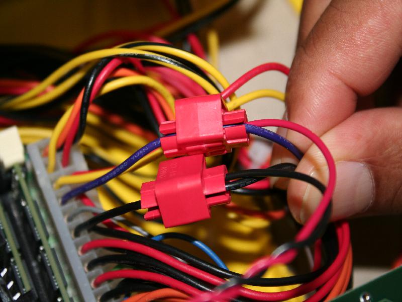
- Attach the red and black power connector wires using the vampire clips to the purple and any black of the 24 pin ATX power supply connector respectively. See image below
 .
.
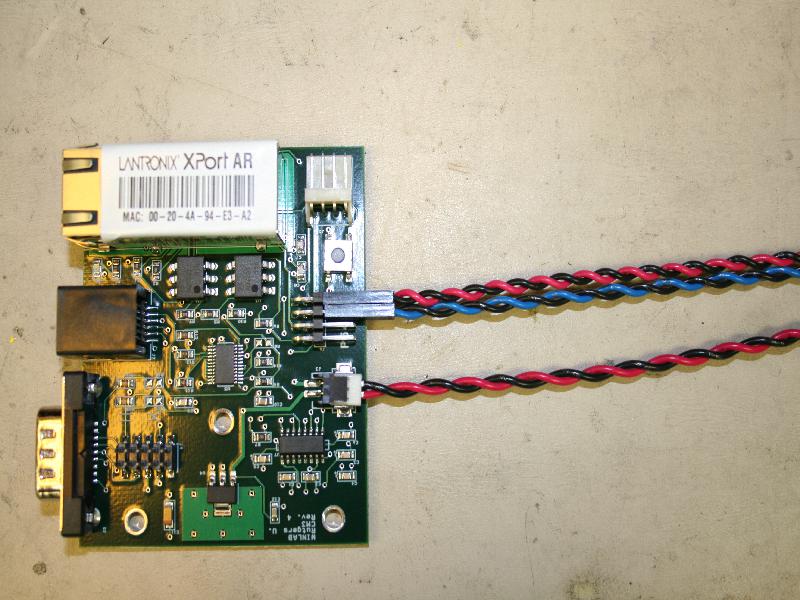
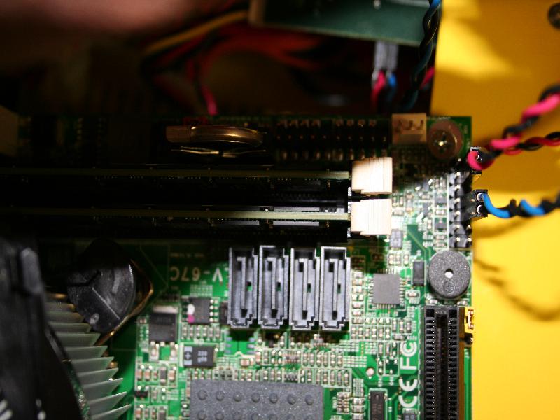
- connect the red/black twisted pair cable to the motherboard, and the other end to the CM as shown in the pictures below. Do the same for the blue/black twisted wire pair. The header on the MB is next to the RAM and SATA connectors.


- Attach the 3 6-32 hex stand offs to the cm card with the 3 6-32 pan head screws. the stand offs should be on the non-component side of the CM
- thread the other end of the serial cable between the 3 stand offs
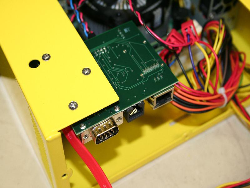
- align the 3 stand offs with the 3 triangle oriented holes on the front left corner of the top of the U chassis.
- thread the other end of the flat serial cable (The other side should be going through slit on top of the face plate) in between the standoffs as to keep it in place and above the fan, them use the 3 3/16" 100 degree screws to attach the cm to the U chassis.
Flashing Full instructions for flashing the CM3 can be found here.
Last modified
13 years ago
Last modified on Jun 18, 2013, 11:59:20 PM
Attachments (4)
-
CmMount.jpg
(69.2 KB
) - added by 13 years ago.
CM mounted in the U-Chassis
-
CmWire.jpg
(98.1 KB
) - added by 13 years ago.
Wires as they should be installed on CM
-
VampClip.jpg
(80.4 KB
) - added by 13 years ago.
Installed vampire clips for CM power
-
CmWireMotherB.jpg
(79.6 KB
) - added by 13 years ago.
Power and Reset command wires on motherboard
Download all attachments as: .zip
Note:
See TracWiki
for help on using the wiki.

