
| Version 5 (modified by , 10 years ago) ( diff ) |
|---|
Under Construction
Basic OAI Tutorial
- WiMAX and LTE Tutorials
- Basic WiMax Operations
- Prerequisites
- Experiment: Image and Ping Nodes Over !WiMAX Interface
- About the Base Station
- Interacting with the Base Station
- Restoring the Base Station to Defaults
- Loading a Default Image
- Manually Confirming Settings
- Connect to the WiMAX Network
- Assign an IP Address
- Repeat for Other Nodes
- Recommended Settings for IP Addresses
- Testing Connection
- Troubleshooting Connectivity Problems
- Basic WiMax Operations
Objective
This objective of this tutorial is to establish a LTE connection between the SDR based UE and eNB. In order to that we need to prepare configuration files on two nodes in sandbox 1, node1-1 and node1-2.
The image was built following the tutorial available at: OAI no S1
Prepare the nodes
- Load the two images with the OAI code to nodes 1-1 and 1-2. This enables running the experiment with no compilation needed.
Load an Image
- Before we begin using the nodes, it's a good idea to check their status first. This is done with the omf stat command.
omf stat
This omf command is used to display the power status of the node/domain.
Usage: omf stat
username@consoles.outdoor:omf stat
Returns the status of the nodes in a testbed
Usage:
      omf-5.4 stat [-h] [-s] [-t TOPOLOGY] [-c AGGREGATE]

      With:
      -h, --help                print this help message
      -s, --summary             print a summary of the node status for the testbed
      -c, --config AGGREGATE    use testbed AGGREGATE
      -t, --topology TOPOLOGY   a valid topology file or description (defaults to 'system:topo:all')

      Some Examples:
                    omf-5.4 stat
                    omf-5.4 stat -s
                    omf-5.4 stat -t omf.nicta.node1,omf.nicta.node2 -c sb1
                    omf-5.4 stat -t system:topo:all -c grid
Individual nodes are identified in the output of stat command by their fully qualified domain name (FQDN). This establishes their "coordinates" and the "domain" to which they belong. Nodes in different domains typically can NOT see each other. Node can be in 1 of 3 states:
POWEROFF Node is Available for use but turned off POWERON Node is Available and is on NOT REGISTERED Node is not Available for use Example: omf stat on the outdoor domain
user@console.outdoor:~# omf stat -t all

 INFO NodeHandler: OMF Experiment Controller 5.4 (git 6d34264)
 INFO NodeHandler: Slice ID: default_slice (default)
 INFO NodeHandler: Experiment ID: default_slice-2012-10-14t14.42.15-04.00
 INFO NodeHandler: Message authentication is disabled
 INFO Experiment: load system:exp:stdlib
 INFO property.resetDelay: value = 210 (Fixnum)
 INFO property.resetTries: value = 1 (Fixnum)
 INFO Experiment: load system:exp:eventlib
 INFO Experiment: load system:exp:stat
 INFO Topology: Loading topology ''.
 INFO property.nodes: value = "system:topo:all" (String)
 INFO property.summary: value = false (FalseClass)
 INFO Topology: Loading topology 'system:topo:all'.
 Talking to the CMC service, please wait
-----------------------------------------------
 Domain: outdoor.orbit-lab.org
 Node: node3-6.outdoor.orbit-lab.org   	 State: NOT REGISTERED
 Node: node3-3.outdoor.orbit-lab.org   	 State: POWEROFF
 Node: node2-10.outdoor.orbit-lab.org    State: POWEROFF
 Node: node1-10.outdoor.orbit-lab.org    State: POWEROFF
 Node: node1-8.outdoor.orbit-lab.org   	 State: POWERON
 Node: node1-6.outdoor.orbit-lab.org   	 State: POWERON
 Node: node3-2.outdoor.orbit-lab.org   	 State: POWEROFF
 Node: node3-1.outdoor.orbit-lab.org   	 State: POWEROFF
 Node: node1-3.outdoor.orbit-lab.org   	 State: POWERON
 Node: node3-5.outdoor.orbit-lab.org   	 State: POWEROFF
 Node: node2-5.outdoor.orbit-lab.org   	 State: NOT REGISTERED
 Node: node1-2.outdoor.orbit-lab.org   	 State: POWERON
-----------------------------------------------
 INFO Experiment: Switching ON resources which are OFF
 INFO EXPERIMENT_DONE: Event triggered. Starting the associated tasks.
 INFO NodeHandler:
 INFO NodeHandler: Shutting down experiment, please wait...
 INFO NodeHandler:
 INFO run: Experiment default_slice-2012-10-14t14.42.15-04.00 finished after 0:6
- It is recommended that the node be in the POWEROFF state prior to any experiment process. If the node is in the POWERON state you can use the omf tell command to get the node into the off state.
omf tell
OMF command to control the power state/reset the nodes.
Usage: omf tell
user@console:omf tell
Switch ON/OFF and reboot the nodes in a testbed
Usage:
      omf tell [-h] -t TOPOLOGY -a ACTION [-c AGGREGATE]

      With:
      -h, --help           print this help message

      -a, --action ACTION  specify an action
      ACTION:
      on              turn node(s) ON
      offs            turn node(s) OFF (soft)
      offh            turn node(s) OFF (hard)
      reboot          reboots node(s) (soft)
      reset           resets node(s) (hard)

      -h, --help                print this help message
      -t, --topology TOPOLOGY   a valid topology file or description (MANDATORY)
      -c, --config AGGREGATE    use testbed AGGREGATE

      Some Examples:
                    omf tell -a reset -t node1-1.grid.orbit-lab.org
                    omf tell -a on -t system:topo:all -c grid
                    omf tell -a reboot -t node1-1
                    omf tell -a offh -t [1..2,1..5]
                    omf tell -a offh -t system:topo:all
                    omf tell -a reset -t system:topo:imaged
The commands are: on, offh (equivalent to pulling out the power cord), offs (software shutdown), reboot (software reboot) and reset (hardware reset).
Example: turn off node1-1 on the outdoor domain
user@console.outdoor:~# omf tell -a offh -t node1-1

 INFO NodeHandler: OMF Experiment Controller 5.4 (git 3fb37b9)
 INFO NodeHandler: Reading configuration file /etc/omf-expctl-5.4/services.yaml
 INFO NodeHandler: Add domain http - http://internal1.orbit-lab.org:5054/
 INFO NodeHandler: Add domain http - http://repository1.orbit-lab.org:5054/
 INFO NodeHandler: Slice ID: default_slice (default)
 INFO NodeHandler: Experiment ID: default_slice-2014-09-30t00.24.28.504-04.00
 INFO NodeHandler: Message authentication is disabled
 INFO Experiment: load system:exp:stdlib
 INFO property.resetDelay: resetDelay = 230 (Fixnum)
 INFO property.resetTries: resetTries = 1 (Fixnum)
 INFO Experiment: load system:exp:eventlib
 INFO Experiment: load system:exp:winlib
 INFO Experiment: load system:exp:tell
 INFO property.nodes: nodes = "node1-1" (String)
 INFO property.command: command = "offh" (String)

Talking to the CMC service, please wait
-----------------------------------------------
 Node: node1-1.outdoor.orbit-lab.org   	 Reply: OK
-----------------------------------------------

 INFO EXPERIMENT_DONE: Event triggered. Starting the associated tasks.
 INFO NodeHandler:
 INFO NodeHandler: Shutting down experiment, please wait...
 INFO NodeHandler:
 INFO run: Experiment default_slice-2014-09-30t00.24.28.504-04.00 finished after 0:10
- Once node set is on an POWEROFF state, load an image with omf load command
omf load
Load command is used to put an image onto the hard disk of the node.
Usage: omf load
Install a given disk image on the nodes in a testbed
Usage:
      omf-5.4 load [-h] [-i IMAGE_PATH] [-o TIMEOUT] [-t TOPOLOGY] [-c AGGREGATE]

      With:
      -h, --help                print this help message
      -c, --config AGGREGATE    use testbed AGGREGATE
      -t, --topology TOPOLOGY   a valid topology file or description (defaults to 'system:topo:all')
                                (if a file 'TOPOLOGY' doesn't exist, interpret it as a comma-separated list of nodes)
      -i, --image IMAGE         disk image to load
                                (default is 'baseline.ndz', the latest stable baseline image)
      -o, --timeout TIMEOUT     a duration (in sec.) after which imageNodes should stop waiting for
                                nodes that have not finished their image installation
                                (default is 800 sec, i.e. 13min 20sec)
          --outpath PATH        Path where the resulting Topologies should be saved
                                (default is '/tmp')
          --outprefix PREFIX    Prefix to use for naming the resulting Topologies
                                (default is your experiment ID)

      Some Examples:
                    omf-5.4 load
                    omf-5.4 load -t system:topo:all -i baseline-2.4.ndz
                    omf-5.4 load -t omf.nicta.node1 -i wireless-2.6.ndz
                    omf-5.4 load -t omf.nicta.node1,omf.nicta.node2 -i baseline.ndz -o 400
                    omf-5.4 load -t system:topo:circle -i my_Own_Image.ndz
                    omf-5.4 load -t my_Own_Topology -i baseline-2.2.ndz -t 600 -c grid
                    omf-5.4 load -t my_Own_Topology --outpath ./ --outprefix my_Own_Prefix
Two important arguments are TOPOLOGY describing the set of nodes one wishes to image , and !IMAGE specifying the name of the image one wants to load the nodes with. If the imaging process does not does not finish within the default timeout period, that period can be increase by using the -o flag (e.g. -o 1600). Typical command to load both nodes of sandbox 1 with the baseline image would look like:
If the node is in the NOT REGISTERED state, you may need to wait for it to recover the POWEROFF state (it some times requires a few moments for the services to sync up). If the node takes more than 60 seconds to come out of the NODE NOT AVAILABLE state please report it to an administrator.Example: omf load-i baseline.ndz -t node1-1
username@console.sb3:~$ omf load -i baseline.ndz -t node1-1

DEBUG FQDN:console.sb3.orbit-lab.org:
 INFO NodeHandler: OMF Experiment Controller 5.4 (git 861d645)
 INFO NodeHandler: Reading configuration file /etc/omf-expctl-5.4/services.yaml
 INFO NodeHandler: Add domain http - http://internal1.orbit-lab.org:5054/
 INFO NodeHandler: Add domain http - http://repository1.orbit-lab.org:5054/
 INFO NodeHandler: Add domain http - http://external1.orbit-lab.org:5054/
 INFO NodeHandler: Slice ID: pxe_slice
 INFO NodeHandler: Experiment ID: pxe_slice-2018-08-08t13.41.37.814-04.00
 INFO NodeHandler: Message authentication is disabled
 INFO Experiment: load system:exp:stdlib
 INFO property.resetDelay: resetDelay = 230 (Fixnum)
 INFO property.resetTries: resetTries = 1 (Fixnum)
 INFO Experiment: load system:exp:eventlib
 INFO Experiment: load system:exp:winlib
 INFO Experiment: load system:exp:imageNode
 INFO property.nodes: nodes = "node1-1" (String)
 INFO property.image: image = "baseline.ndz" (String)
 INFO property.domain: domain = "sb3.orbit-lab.org" (String)
 INFO property.outpath: outpath = "/tmp" (String)
 INFO property.outprefix: outprefix = "pxe_slice-2018-08-08t13.41.37.814-04.00" (String)
 INFO property.timeout: timeout = 800 (Fixnum)
 INFO property.resize: resize = nil (NilClass)
 INFO Topology: Loaded topology 'system:topo:registered'.
 INFO property.resetDelay: resetDelay = 100 (Fixnum)
 INFO Experiment: Resetting resources
 INFO stdlib: Waiting for nodes (Up/Down/Total): 0/1/1 - (still down: node1-1.sb3.orbit-lab.org) [0 sec.]
 INFO stdlib: Waiting for nodes (Up/Down/Total): 0/1/1 - (still down: node1-1.sb3.orbit-lab.org) [10 sec.]
 INFO stdlib: Waiting for nodes (Up/Down/Total): 0/1/1 - (still down: node1-1.sb3.orbit-lab.org) [20 sec.]
 INFO stdlib: Waiting for nodes (Up/Down/Total): 0/1/1 - (still down: node1-1.sb3.orbit-lab.org) [30 sec.]
 INFO stdlib: Waiting for nodes (Up/Down/Total): 0/1/1 - (still down: node1-1.sb3.orbit-lab.org) [40 sec.]
 INFO stdlib: Waiting for nodes (Up/Down/Total): 0/1/1 - (still down: node1-1.sb3.orbit-lab.org) [50 sec.]
 INFO exp: Progress(0/0/1): 0/0/0 min(node1-1.sb3.orbit-lab.org)/avg/max (59) - Timeout: 790 sec.
 INFO ALL_UP: Event triggered. Starting the associated tasks.
 INFO BRING_UP: Event triggered. Starting the associated tasks.
 INFO Experiment: Bringing up resources
 INFO exp: Progress(0/0/1): 50/50/50 min(node1-1.sb3.orbit-lab.org)/avg/max (59) - Timeout: 780 sec.
 INFO exp: Progress(0/0/1): 80/80/80 min(node1-1.sb3.orbit-lab.org)/avg/max (59) - Timeout: 770 sec.
 INFO exp: Progress(1/0/1): 100/100/100 min()/avg/max (59) - Timeout: 760 sec.
 INFO exp:  -----------------------------
 INFO exp:  Imaging Process Done
 INFO exp:  1 node successfully imaged - Topology saved in '/tmp/pxe_slice-2018-08-08t13.41.37.814-04.00-topo-success.rb'
 INFO exp:  -----------------------------
 INFO EXPERIMENT_DONE: Event triggered. Starting the associated tasks.
 INFO NodeHandler:
 INFO NodeHandler: Shutting down experiment, please wait...
 INFO NodeHandler:
 INFO NodeHandler: Shutdown flag is set - Turning Off the resources
 INFO run: Experiment pxe_slice-2018-08-08t13.41.37.814-04.00 finished after 1:44
- Before we begin using the nodes, it's a good idea to check their status first. This is done with the omf stat command.
- Load the eNB image to node1-1.
omf load -t node1-1 -i mf-oai-enb.ndz
- Load the UE image to node1-2.
omf load -t node1-2 -i mf-oai-ue.ndz
omf tell -a on -t system:topo:imaged
Turn the Nodes ON
To turn the nodes on use omf tell command:
omf tell
OMF command to control the power state/reset the nodes.
Usage: omf tell
user@console:omf tell
Switch ON/OFF and reboot the nodes in a testbed
Usage:
      omf tell [-h] -t TOPOLOGY -a ACTION [-c AGGREGATE]

      With:
      -h, --help           print this help message

      -a, --action ACTION  specify an action
      ACTION:
      on              turn node(s) ON
      offs            turn node(s) OFF (soft)
      offh            turn node(s) OFF (hard)
      reboot          reboots node(s) (soft)
      reset           resets node(s) (hard)

      -h, --help                print this help message
      -t, --topology TOPOLOGY   a valid topology file or description (MANDATORY)
      -c, --config AGGREGATE    use testbed AGGREGATE

      Some Examples:
                    omf tell -a reset -t node1-1.grid.orbit-lab.org
                    omf tell -a on -t system:topo:all -c grid
                    omf tell -a reboot -t node1-1
                    omf tell -a offh -t [1..2,1..5]
                    omf tell -a offh -t system:topo:all
                    omf tell -a reset -t system:topo:imaged
The commands are: on, offh (equivalent to pulling out the power cord), offs (software shutdown), reboot (software reboot) and reset (hardware reset).
Example: turn off node1-1 on the outdoor domain
user@console.outdoor:~# omf tell -a offh -t node1-1

 INFO NodeHandler: OMF Experiment Controller 5.4 (git 3fb37b9)
 INFO NodeHandler: Reading configuration file /etc/omf-expctl-5.4/services.yaml
 INFO NodeHandler: Add domain http - http://internal1.orbit-lab.org:5054/
 INFO NodeHandler: Add domain http - http://repository1.orbit-lab.org:5054/
 INFO NodeHandler: Slice ID: default_slice (default)
 INFO NodeHandler: Experiment ID: default_slice-2014-09-30t00.24.28.504-04.00
 INFO NodeHandler: Message authentication is disabled
 INFO Experiment: load system:exp:stdlib
 INFO property.resetDelay: resetDelay = 230 (Fixnum)
 INFO property.resetTries: resetTries = 1 (Fixnum)
 INFO Experiment: load system:exp:eventlib
 INFO Experiment: load system:exp:winlib
 INFO Experiment: load system:exp:tell
 INFO property.nodes: nodes = "node1-1" (String)
 INFO property.command: command = "offh" (String)

Talking to the CMC service, please wait
-----------------------------------------------
 Node: node1-1.outdoor.orbit-lab.org   	 Reply: OK
-----------------------------------------------

 INFO EXPERIMENT_DONE: Event triggered. Starting the associated tasks.
 INFO NodeHandler:
 INFO NodeHandler: Shutting down experiment, please wait...
 INFO NodeHandler:
 INFO run: Experiment default_slice-2014-09-30t00.24.28.504-04.00 finished after 0:10
Execute the experiment
If you intend to use graphical user interface please make sure to install appropriate tools on your local machine and configure X11 forwarding.
Remote Graphical Access
Table of Contents
We really don't want to encourage this too much since it depends on network performance especialy on slow links. In ORBIT, remote graphical access is a two step process: tunneling from your local machine to the console of the domain you are working on that is followed by tunneling from the console to the node. Assumption is that one is using Linux baseline images and thus X Window System (X11) based graphical environment.
Remote X11 Access For Linux
Simply use the -X or -Y flags, e.g. for remote graphical access to node1-1.sb1.orbit-lab.org:
ssh -Y -t sb1.orbit-lab.org ssh -Y -t root@node1-1If you get an error about ssh keys not matching, you MUST follow the instructions for configuring your ssh keys; you will not b able to do X11 forwarding until this problem is fixed.
Remote X11 Access For Windows
In addition to ssh client, remote X11 access on Windows requires installation of X11 Server. Number of open source or free servers is available including:
- VcXsrv
- Xming
- mobaXterm (includes ssh client)
to name a few.
As an illustration, we will use configuration based on Putty and VcXsrv and connect with remote graphics capability to the node1-1.sb1:
- Install Putty and make sure you can log into ORBIT gateway or console
- Install VcXsrv and make sure it is running say on display 1 (without any applications)
- Start Putty and load the appropriate session
- Configure X11 forwarding under "Connection→SSH→X11":
- Check mark on "Enable X11 forwarding"
- Set "X display location" to: 127.0.0.1:1 (note matching display number)
- Save the session
- Open the session to SB1 i.e. connect to the console.sb1.orbit-lab.org
- On the console execute
ssX -Y -t root@node1-1and connect to the node.
Remote X11 Access For MAC
- Mac: You must use an X11 capable ssh client such as FIXME, or install a standalone X11 client such as FIXME
- Start x11 capable client
- SSH to console
- SSH to node
Quickstart Option
We have an image available, named oai-dev.ndz. It has all the necessary driver and software pre-installed, and two scripts available to immediately boot up the eNB and UE. This quickstart assumes use of Sandbox1, nodes 1-1, and 1-2.
- To proceed, after having a reservation, load the following image.
omf load -t node1-1,node1-2 -i oai-dev.ndz- The nodes will automatically turn off when imaging is completed.
- Turn the nodes on.
omf tell -a on -t node1-1,node1-2
- Open a terminal to each node. You must enable X11 Forwarding to see the GUI and statistics screens.
- You will need at lease one terminal per node, for the statistics screens. Even more if you want to run additional commands. For details, refer to the Remote Graphical Access section.
- On the first node, execute script
./CompandRuneNB - On the second node, execute script
./CompandRunUE - For subsequent runs, execute
./runeNBor./runUEinstead, to avoid recompiling. - These scripts will create interface
oai0and assign an address.- Use
ifconfigorip ato see the address assigned. - By default the eNB has address 10.0.1.1, and the UE has addresss 10.0.1.9, but you should double check.
- Use
- You should be able to ping from one node to the other on these addresses.
- From UE,
ping 10.0.1.1or to see live statisticsmtr 10.0.1.1
- From UE,
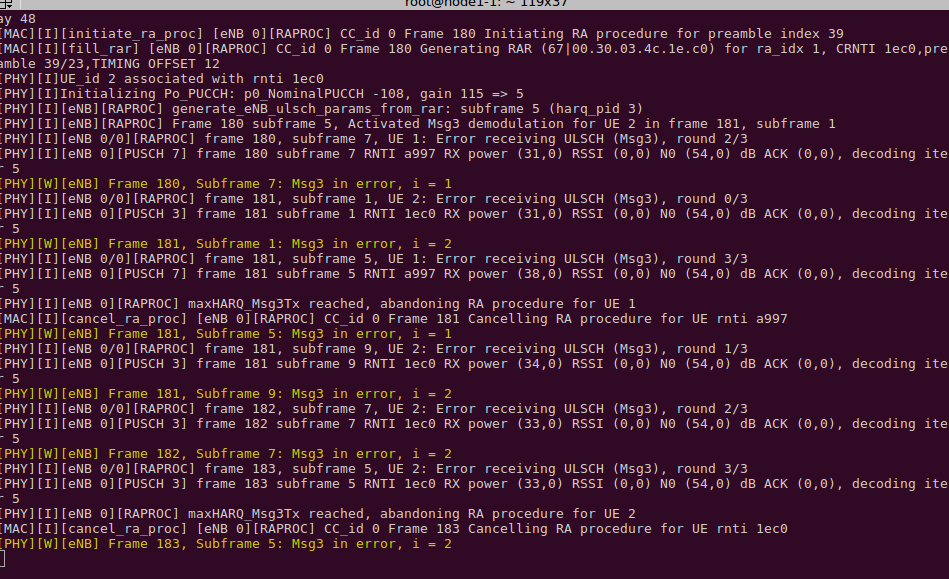
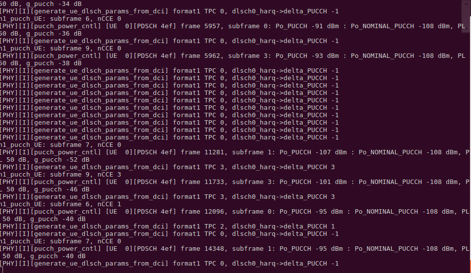
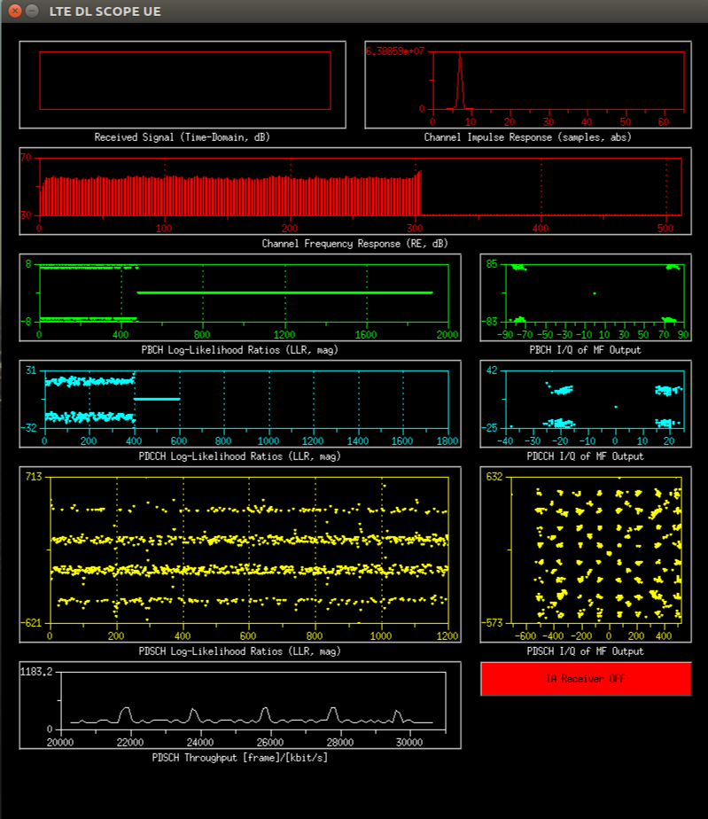
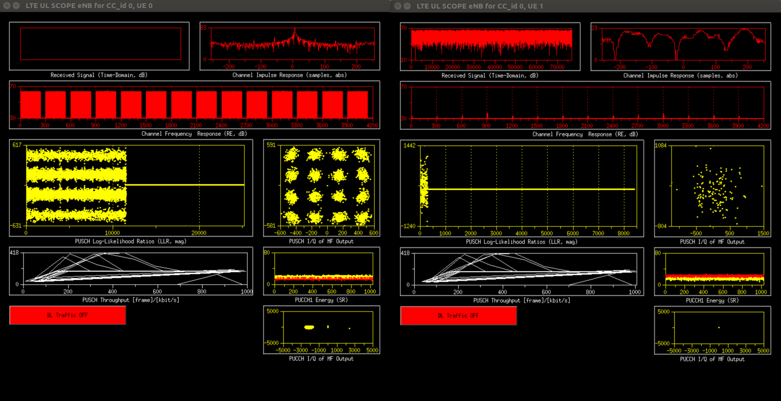
In your terminals, you will see the following screens upon successful script execution.


OAI eNB in ORBIT
UNDER DEVELOPMENT
- Load image lte-edge.ndz to a node with a b210
- This can be found from the status page
- Turn the node on
- SSH to the node
cd /opt- Run
./setup.sh --build_enb_ue - Edit the configuration file to match the needed IP using the editor of your choice (example vim)
vim ./conf/enb.band25.tm1.usrpb210.conf- The MME ip address is on the line
mme_ip_address = ( { ipv4 = "10.3.0.21";- Do not change this unless you are using a custom MME, rather than the ORBIT hosted one, or are tunneling.
- Set the following four lines to match the interface you will use to connect to the MME. In this example it is set to use eth1 on node8-7.grid.orbit-lab.org.
ENB_INTERFACE_NAME_FOR_S1_MME            = "eth0";
ENB_IPV4_ADDRESS_FOR_S1_MME              = "10.40.4.5/16";
ENB_INTERFACE_NAME_FOR_S1U               = "eth0";
ENB_IPV4_ADDRESS_FOR_S1U                 = "10.40.4.5/16";
- Run the eNB
./openairinterface5g/cmake_targets/lte_build_oai/build/lte-softmodem -O ./conf/enb.band25.tm1.usrpb210.conf- Some options to append
- -d : shows visual displays
- Some options to append