| Version 51 (modified by , 3 years ago) ( diff ) |
|---|
Grid
Table of Contents
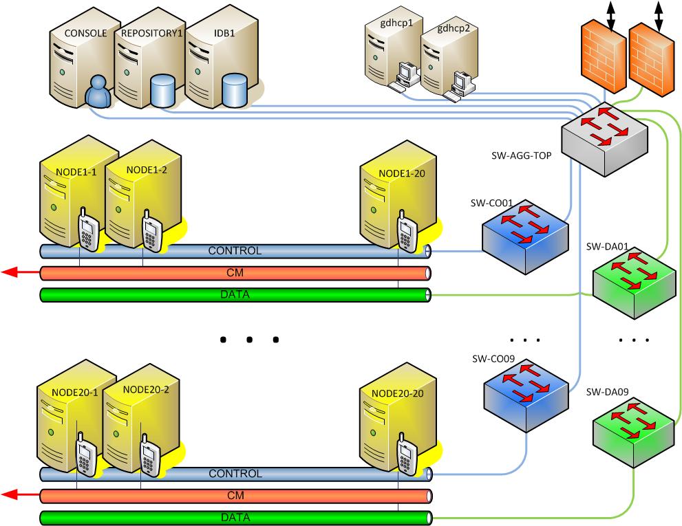
Block diagram of the ORBIT Grid domain is shown in Figure 1. The main components of this domain are:
- Grid nodes: 20 x 20 machines arranged in a grid configuration (20 rows with 20 nodes each) with spacing of 3 feet.
- Massive-MIMO racks: four mini-racks of SDRs with 32 antennas each
- Servers: number of servers of varying capabilities
- Virtual machines: number of on-demand VM instances
- Noise injection subsystem: for injecting arbitrary signals to create different topologies
- Support infrastructure: SDN capable ethernet switches, GPS/RF reference distribution, console and other support hardware

Figure 1: ORBIT GRID
Massive-MIMO mini-racks
There are four mini-racks located in the corners of the Grid specifically for massive-MIMO experiments. Each rack contains 8 Ettus USRP X310 software defined radios outfitted with two UBX 160 radio daughterboards each. Unlike USRPs in the main 20x20 Grid which are direct attached to individual nodes, each USRP in the mini-racks is connected via 10G ethernet to the rest of the Grid domain and appear as nodes (node23-1 through node23-8) that respond to standard OMF power commands and are visible/accessible on the network by any other node on the grid domain. PPS and 10MHz synchronization signals are distributed among the USRPs in each rack via an Octoclock based timing distribution system. Equal length cables are used to ensure minimum timing deviation within and between the racks allowing for all USRPs across the four racks to by synchronized. Additional hardware is present in each rack to allow for power-cycling and "imaging" of the USRPs in a similar manner to standard nodes.

Figure 2: Massive-MIMO mini-rack
Location Node Massive-MIMO Mini-Rack
under node1-123-1, 23-2, 23-3, 23-4, 23-5, 23-6, 23-7, 23-8 Massive-MIMO Mini-Rack
under node1-2023-11, 23-12, 23-13, 23-14, 23-15, 23-16, 23-17, 23-18 Massive-MIMO Mini-Rack
under node20-124-1, 24-2, 24-3, 24-4, 24-5, 24-6, 24-7, 24-8 Massive-MIMO Mini-Rack
under node20-2024-11, 24-12, 24-13, 24-14, 24-15, 24-16, 24-17, 24-18
The top of each Massive-MIMO mini-rack is populated with a horizontal array of 32 antennas. They are mounted on a rectangular plate with a 2 inch spaced grid pattern. See table below for antenna location to USRP mapping.
Example antenna configuration (top-down view) for node23-1 through node23-8:
Back of Massive-MIMO mini-rack 23-1 RF A TX/RX 23-1 RF A RX2 23-1 RF B TX/RX 23-1 RF B RX2 23-2 RF A TX/RX 23-2 RF A RX2 23-2 RF B TX/RX 23-2 RF B RX2 23-3 RF A RX2 23-3 RF A TX/RX 23-3 RF B RX2 23-3 RF B TX/RX 23-4 RF A RX2 23-4 RF A TX/RX 23-4 RF B RX2 23-4 RF B TX/RX 23-5 RF A TX/RX 23-5 RF A RX2 23-5 RF B TX/RX 23-5 RF B RX2 23-6 RF A TX/RX 23-6 RF A RX2 23-6 RF B TX/RX 23-6 RF B RX2 23-7 RF A RX2 23-7 RF A TX/RX 23-7 RF B RX2 23-7 RF B TX/RX 23-8 RF A RX2 23-8 RF A TX/RX 23-8 RF B RX2 23-8 RF B TX/RX Front of Massive-MIMO mini-rack
Servers
A number of high CPU core count/large memory servers are available for running "back-end" software. Some are equipped with GPUs for increased computational performance.
Virtual Machines
A virtual machine infrastructure is provided to facilitate on-demand creation of additional "nodes" which can be used to run: non-performance critical back-end software, various controllers, or monitoring and reporting tools.
Noise Injection subsystem
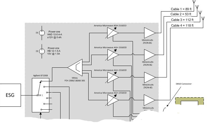
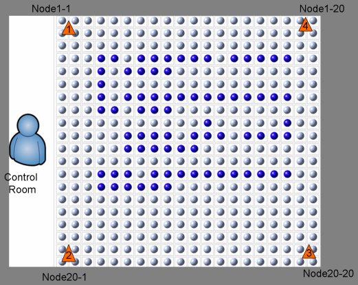
The Centralized Arbitrary Waveform Injection Subsystem (CAWIS) consists of arbitrary waveform generator (Agilent ESG) connected through a distribution network to four multi-band antennas located in the four corners of the grid. The distribution network enables control over the attenuation of the individual antenna feed. Using CAWIS, users can inject (among other types of waveforms) AWGN signals into the main ORBIT grid and thus create different topologies.
Noise Antennas in the Grid
Figure 2: CAWIS 

a.) Block Diagram b.) Noise injection antenna positions
As most of the Orbit services, CAWIS is a web-based service accessible from the main grid console through url: http://instrument1.orbit-lab.org:5054/interference. As with other aggregate managers, accessing this url without any other arguments will show it's usage reference page.
Support Infrastructure
The ORBIT Grid domain has many systems and hardware in place to facilitate running experiments. SDN capable switches are provided on the dedicated Data network for users to reconfigure as necessary. The timing synchronization system not only permits the massive-MIMO mini-racks to be synchronized, but also certain corner nodes in the main Grid as well. Additionally, a console machine is provided for jump access to the Grid nodes and for control of experiments and domain specific hardware.
Synchronized Clock Reference (Octoclock)
The Massive-MIMO mini-racks and several SDRs in the grid are connected to a GPS-disciplined clock reference system which gives the SDRs PPS (pulse per second) and 10MHz reference signals for synchronizing their internal oscillators. A tree-like topology with equal length cables ensures minimal deviation of the reference signals between connected devices. The following nodes have SDRs that are currently connected to this clock reference system:
Location Node 1-1 Corner 1-1, 1-2, 2-1, 2-2, 3-1, 3-2 1-20 Corner 1-19, 1-20, 2-19, 2-20, 3-19, 3-20, 4-19, 4-20 20-1 Corner 17-1, 17-2, 18-1, 18-2, 19-1,19-2, 20-1, 20-2 20-20 Corner 18-19, 18-20, 19-19, 19-20, 20-19, 20-20
Massive-MIMO Mini-Rack
under node1-123-1, 23-2, 23-3, 23-4, 23-5, 23-6, 23-7, 23-8 Massive-MIMO Mini-Rack
under node1-2023-11, 23-12, 23-13, 23-14, 23-15, 23-16, 23-17, 23-18 Massive-MIMO Mini-Rack
under node20-124-1, 24-2, 24-3, 24-4, 24-5, 24-6, 24-7, 24-8 Massive-MIMO Mini-Rack
under node20-2024-11, 24-12, 24-13, 24-14, 24-15, 24-16, 24-17, 24-18
For more information, see the Clock Reference page.
Attachments (5)
- noiseantenna.png (197.6 KB ) - added by 19 years ago.
-
ORBITGridBD.jpg
(114.3 KB
) - added by 13 years ago.
ORBIT Grid Block Diagram
-
CAWIS.jpg
(70.4 KB
) - added by 13 years ago.
Interference Injection Subsystem Block Diagram
-
Massive-MIMO.jpg
(163.8 KB
) - added by 10 years ago.
Massive-MIMO mini-rack
- APAMSJ-137.pdf (2.0 MB ) - added by 3 years ago.
